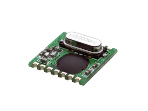
Recently, I found some cheap HOPERF RFM01/02 433 MHz radio transmitter/receivers for only ~3 € each, so I couldn’t resist to buy some. I had on my mind to build a device for wireless transmission of sensor data, such as temperature, wind speed or humidity, using a Raspberry Pi or Arduino UNO as a receiver.
Some research on the web revealed that this could be a difficult task, however I was eager to give it a try, since the XBEE RF Arduino modules are much more expensive.
Wiring of the modules to a microcontroller
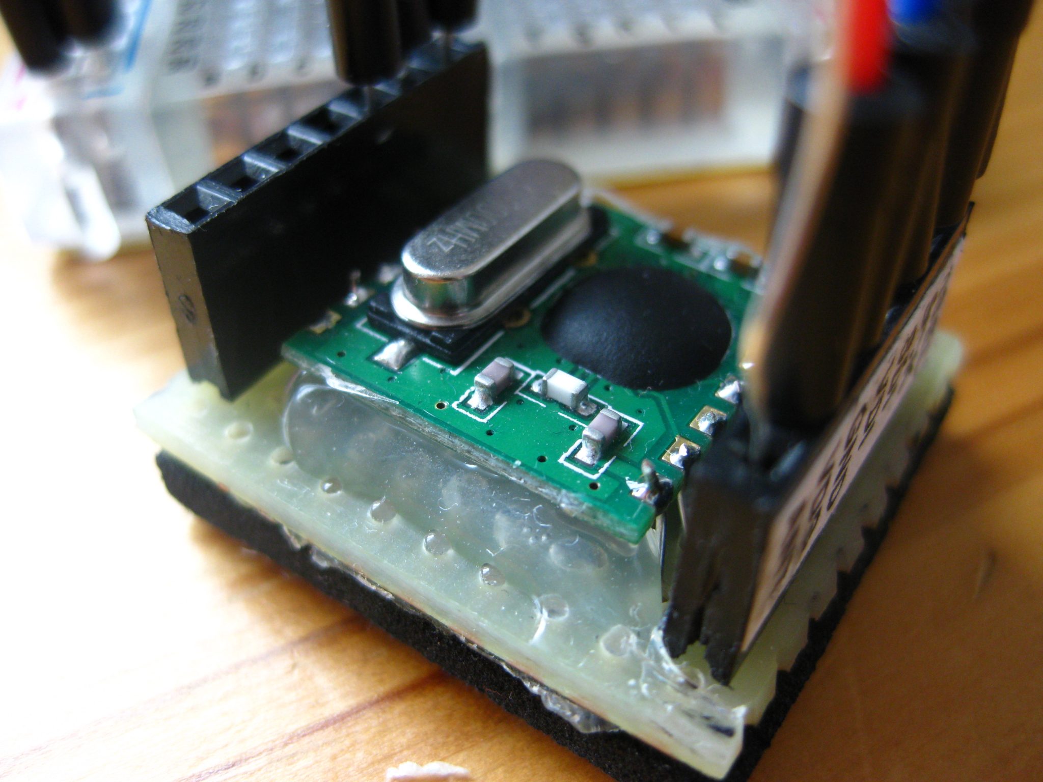
I purchased the SMD variant of the modules. Therefore, it was necessary to solder them onto a stripe-board with two 1×7 female headers on both sides. The pin spacing of the modules is not 2.54 mm, so it was necessary to solder a short piece of copper wire to each pin. After soldering, I fixed the modules using some hot glue, for better protection against physical stress. A ~17 cm (0.5 mm diameter) copper wire serves as an antenna (optimum length of the antenna is about 17.5 cm, if it is soldered directly to the module).
 Now, both modules were ready for prototyping and I started experimenting with RFM02 connected to a stand-alone ATMega328P (with 8 MHz internal oscillator). On https://www.mikrocontroller.net I found more than 100 discussion threads about the RFM12B transceiver module, which is similar to RFM01/02 but able to both transmit and receive data.
From the threads I extracted the connection scheme below, which in fact saved me from re-inventing the wheel …
| RFM02 | ATMEGA328P |
| SDI | PB0 (physical pin14) |
| SCK | PB1 (physical pin15) |
| nSEL | PB2 (physical pin 16) |
| VCC | +5 Volt |
| GND | GND |
| FSK | via 10k resistor to +5 Volt |
| nIRQ | PB4 (physical pin18) |
| physical pin7 to +5 Volt | |
| physical pin8 to GND | |
| physical pin1 via 10k resistor to +5 Volt, (optional) physical pin1 via 100 nF ceramic capacitor to GND for programming with serial TTL adapter |
|
| physical pin20 to + 5 Volt | |
| physical pin21 to + 5 Volt | |
| physical pin22 to GND | |
| physical pin6 to LED1 (+), connect the (-) LED pin to GND | |
| physical pin11 to LED2 (+), connect the (-) LED pin to GND | |
| physical pin12 to DS18S20 data pin (with 4.7k resistor between +5 Volt and data pin of DS18S20) |
I attached the RFM01 receiver to a breadboard Arduino with 16 MHz external oscillator and a 2×16 LCD display with self-made 74HC595 backpack (with the clock, latch and data pin wired to PD5, PD6 and PD7 of the ATmega328).
| RFM01 | ATMEGA328P |
| SDO | PB2 (physical pin16) |
| nIRQ | PD2 (physical pin4) |
| nFFS | to +5 Volt via 10k resistor |
| nSEL | PB3 (physical pin17) |
| SCK | PB4 (physical pin18) |
| SDI | PB5 (physical pin19) |
| physical pin7 to +5 Volt | |
| physical pin8 to GND | |
| physical pin1 via 10k resistor to +5 Volt, (optional) physical pin1 via 100 nF ceramic capacitor to GND for programming with serial TTL adapter |
|
| physical pin20 to + 5 Volt | |
| physical pin21 to + 5 Volt | |
| physical pin22 to GND | |
| physical pin 9 to 16 MHz crystal (each crystal pin is connected to GND via 22 pF ceramic capacitor) | |
| physical pin 19 to 16 MHz crystal (each crystal pin is connected to GND via 22 pF ceramic capacitor) |