In order to get data from devices producing analog output, for example a light-dependent resistor (LDR) or potentiometer, it is necessary to connect an analog-to-digital converter (ADC) to the RasPi. In contrast to the Arduino UNO, there are no analog pins on Pi’s GPIO header.
With the MCP3008 one can add up to eight analog I/O channels with 10 bit resolution. MCP3008 communicates with the Pi using the SPI bus . The voltage on channel 0-7 relative to VREF will be reported as value between 0 and 1023.
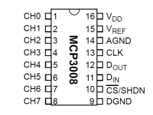
Wiring to the SPI bus
To get started, make the following connections between MCP3008 and your RasPi:.
| MCP3008 | RasPi |
| VDD | +3.3V |
| VREF | +3.3V, Reference Voltage |
| AGND | GND |
| CLK | CLK (pin 23) |
| DOUT | MISO (pin 21), Master Input Slave Out |
| DIN | MOSI (pin 19), Master Output Slave In |
| CS | CE0 (pin 24), Chip Select |
| DGND | GND |
Enable SPI on the RasPi
To enable SPI, you must comment or remove the line spi_bcm2708 from /etc/modprobe.d/raspi-blacklist.conf. Then, reboot or load the module with modprobe.
In order to test if the SPI kernel module was successfully loaded, short the MISO and MOSI pin with a patch wire. Then, download a file from github:
wget https://raw.githubusercontent.com/raspberrypi/linux/rpi-3.10.y/Documentation/spi/spidev_test.c
(N.B: the code linked in [2] did not compile on a Raspi, but this link works)
In the file spidev_test.c, change spidev1.1 to spidev0.0. Now, compile and run the program:
$ gcc spidev_test.c
$ ./a.out
If SPI is active, and with MISO and MOSI connected to each other, you should see the following output:
spi mode: 0
bits per word: 8
max speed: 500000 Hz (500 KHz)

FF FF FF FF FF FF
40 00 00 00 00 95
FF FF FF FF FF FF
FF FF FF FF FF FF
FF FF FF FF FF FF
DE AD BE EF BA AD
F0 0D
Next, install the SPI python-wrapper from the git repository:
$ git clone git://github.com/doceme/py-spidev
$ cd
$ cd py-spidev
$ sudo python setup-py install
To read SPI data from the chip, use the following Pyhon code:
import spidev
import time

spi = spidev.SpiDev()
spi.open(0,0)

#read SPI from MCP3008 chip, 8 possible chanels
def readadc(adcnum):
        if ((adcnum > 7) or (adcnum < 0)):
                return -1
        r = spi.xfer2([1,(8+adcnum)<<4,0])
        adcout = ((r[1]&3) << 8) + r[2]
        return adcout

#chanel input on ADC
ch0 = 0

while 1:
        #read chanel
        pc_value0 = readadc(ch0)

        #print data from ADC
        print pc_value0

        #wait do nothing for 0.20 sek
        time.sleep(0.5)
References:
- Interfacing an SPI ADC (MCP3008) chip to the Raspberry Pi using C++ (spidev)
-
SPI-Python: Hardware SPI for RasPi from Python
-
Raspberry Pi hardware SPI analog inputs using the MCP3008
- Adafruit MCP3008 – 8-Channel 10-Bit ADC With SPI Interface