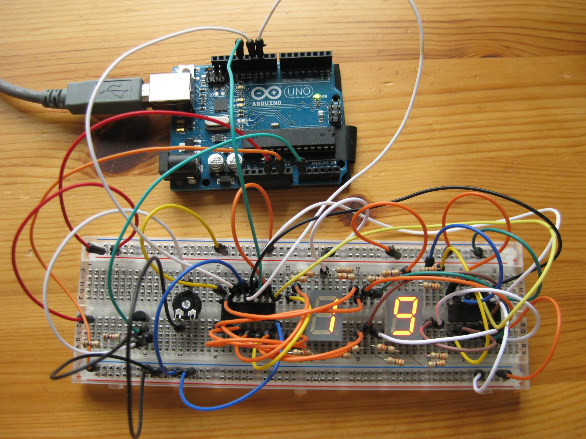
Assembling and testing circuits on an Arduino UNO
Since the GPIO pins of the Raspberry Pi are somewhat sensitive to current higher than 20 mA, the Arduino UNO provides a safe testing platform to develop new wiring diagrams and circuits before connecting them to a Raspberry Pi. Furthermore, it’s a nice learning tool for microelectronics, physical computing and microcontroller programming.
Most of the sensors which can be used on a RasPi will also work with the Arduino UNO. As a starting point, I purchased a Fritzing super upgrade kit which contains a lot of parts to get started with some experiments. One of my first projects was an Arduino UNO thermometer, showing the temperature read from an analog LM335Z sensor on two 7-segment LED displays.
Measuring temperature with the analog LM335Z temperature sensor
Parts list
- 2 x Kingbright 7-segments display (SA52-11EWA, common Anode)
- 16 x 330 Ω resistor (orange, orange, red)
- 1 x 2 kΩ resistor
- 1 x 10 kΩ variable resistor
- 2 x shift register (M74HC595)
- 1 x LM335Z analog temperature sensor
- breadboard
- M/M jumper wires
Wiring of shift registers to the 7-segment displays
7-segment displays are probably the most simple devices that one can use for displaying digital numbers. They consist of 8 LED segments which can be lit up individually. There are two types of displays available, with either a common cathode or a common anode .
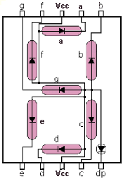
The VCC pin is attached to +5V on the Arduino UNO. The LEDs have a forward voltage of about VF = 2.0 V. Therefore, a resistor of at least 150 Ω (5 – 2 / 0.02) is required as a multiplier. Here I use 330 Ω which will make the LEDs more dim. Each segment of the display can be connected to a digital pin of the Arduino UNO. In order to light one of the segments up, it’s respective digital pin must be pulled HIGH or LOW (common anode -> LOW, common kathode HIGH). In this tutorial I use displays with a common anode.
The status of the eight LEDs can be represented as a series of bits, such as 0 0 0 0 0 0 0 0 for a fully lit display or 0 0 1 0 0 0 1 0 with only two segments lit up. Although it is possible to attach one 7-segment display directly to the Arduino UNO, there are not enough digital pins available to connect two displays at once. However, with a so-called shift register it is possible to multiply the number of pins on an Arduino UNO. Instead of controlling the LED display directly, the Arduino UNO sends a serial signal to the shift register for controlling it’s output pins.
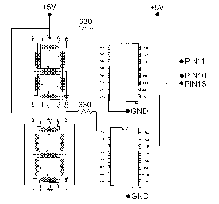
Thus, each display is connected to a shift register. The M74HC595 shift register has eight output pins QA – QH which are wired to the eight pins (segments) of the display. For the example shown here, I attached the QA pin of the shift register to segment “a” of the display, QB to segment “b”, QC to “c” and so forth. The “dp, digital point” segment is wired to QH.
 The register itself requires only three digital pins on the Aduino, i.e. for SERIAL IN (SI), RCK and SCK. The SERIAL IN of the second shift register is connected to the SERIAL OUT (pin 9) of the first register.
In order to tell the shift registers which of the pins QA – QH to be pulled HIGH or LOW, two series of bits are sent through a “serial bus” to the register. For example 1 0 0 1 1 1 1 1 0 0 0 0 0 0 1 1 to show a “10” on the display. The series of bits is transferred from the right to the left in order to show a “0” on the second display and a “1” on the first display. This type of transfer mode is called LSBFIRST or “last significant bit first”.