Debugging of newly developed ATtiny45/85 sketches turned out to be complicated due to the lack of an sufficient amount of output pins. USB-to-TTL-serial converters are excellent tools for this purpose. With the RX pin of the adapter attached to an ATtiny pin, one can receive it’s output by using the serial monitor of the Arduino IDE.
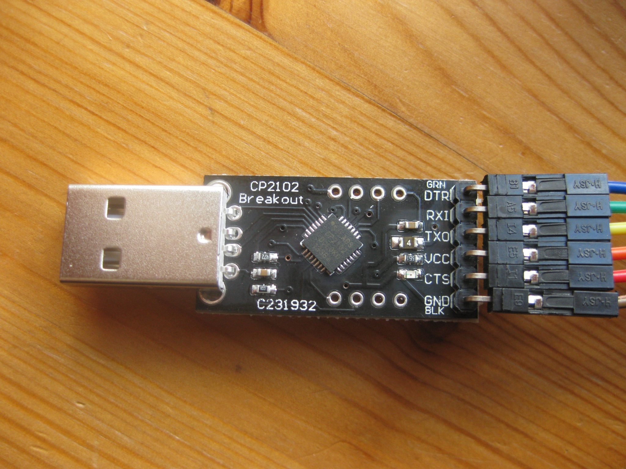
There are many cheap (less than 5 Euro) adapters available. If you’re going to use it as an ISP programmer for a standalone ATMega328, you must make sure that it’s DTR pin is exposed as discussed here. Otherwise it is necessary to modify the adapter as described in this post. I have ordered an adapter with a Silicon Labs CP2102 chip. It doesn’t require installation of a driver under Linux. However, Windows needs a driver which can be downloaded from the Silicon Labs page.
In order to test it on an ATtiny45, I uploaded a sketch sending a text string to the serial output. Make sure to use a TinyCore including SoftwareSerial.h, otherwise the sketch won’t compile.
void setup() {
  Serial.begin(9600);
}
void loop() {
  Serial.println("Hello World!");
  delay(1000);
  Serial.println(12345);
  delay(1000);
}
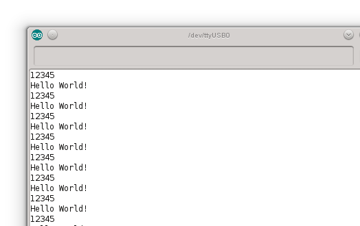
After uploading the sketch, connect GND to Pin4, VCC to Pin 8 and RX of the adapter to ATtiny45 Pin2. Then, open the serial monitor. You should see the following output: