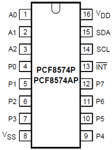
If you’re short of GPIO pins on your RasPi, the PCF8574 port expander can help to increase the number of I/O pins for your project. PCF8574 requires only two GPIO pins on your Pi and gives access to eight extra I/O pins (P0 – P7) using the I2C bus.
Wiring of PCF8574 to the Raspberry Pi
Before you begin, make sure that the i2c_bcm2708 and i2c-dev kernel modules are loaded (you can check that with “lsmod”). On a freshly installed Raspbian Wheezy, the modules are disabled by default and must be enabled by commenting (#) or removing the respective lines in /etc/modprobe.d/raspi-blacklist.conf. In order to load the modules at boot time, create an entry for both kernel modules in /etc/modules. Furthermore, install the i2c-tools with:
$ sudo apt-get update
$ sudo apt-get install i2c-tools
$ sudo apt-get install python-smbus
Now, check if the kernel modules are present by typing:
$ sudo i2c-detect -y 1
(on a Raspberry Pi Rev. 1, you must use -y 0 as a parameter). With no I2c devices connected, you should see an output like this:
     0  1  2  3  4  5  6  7  8  9  a  b  c  d  e  f
00:          -- -- -- -- -- -- -- -- -- -- -- -- --
10: -- -- -- -- -- -- -- -- -- -- -- -- -- -- -- --
20: -- -- -- -- -- -- -- -- -- -- -- -- -- -- -- --
30: -- -- -- -- -- -- -- -- -- -- -- UU -- -- -- --
40: -- -- -- -- -- -- -- -- -- -- -- -- -- -- -- --
50: -- -- -- -- -- -- -- -- -- -- -- -- -- -- -- --
60: -- -- -- -- -- -- -- -- -- -- -- -- -- -- -- --
70: -- -- -- -- -- -- -- --
Wiring to the RasPi is straightforward: simply connect the SDA and SCL pins of PCF8574 to the SDA and SCL pin of your Pi, physical pin 3 and 5, respectively. Connect, VDD to 3.3 Volt and VSS to GND.
 I2C addressing
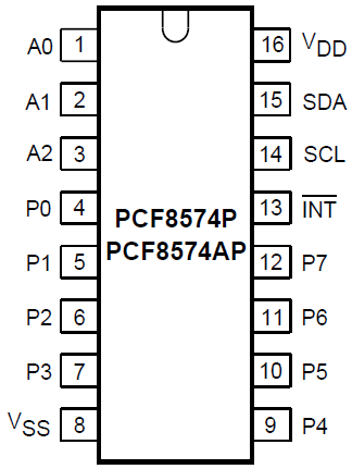
It is possible to control multiple PCF8574 expanders connected to the same SDA and SCL pins on your Pi. However, each device must have its own, unique I2C address. With the pins A0 – A2 you can set a unique identifier for each of your PCF8474 expanders, by wiring them either to GND (LOW) or to + 3.3 Volt (HIGH). If you set the pins to HIGH, you should use a 10 kΩ pullup resistor between +3.3V and the A pin. Depending on the IC variant that you use (check whether you’ve got a PCF8574 or PCF8574A), the slave address can be set according to the following table:
| Inputs | Slave I2C Adresses (Hexadecimal Value) |
|||
| A0 | A1 | A2 | PCF8574 | PCF8574A |
| L | L | L | 0x20 | 0x38 |
| L | L | H | 0x21 | 0x39 |
| L | H | L | 0x22 | 0x3A |
| L | H | H | 0x23 | 0x3B |
| H | L | L | 0x24 | 0x3C |
| H | L | H | 0x25 | 0x3D |
| H | H | L | 0x26 | 0x3E |
| H | H | H | 0x27 | 0x3F |
With all A pins wired to GND, i2c-detect should produce an output like this:
     0  1  2  3  4  5  6  7  8  9  a  b  c  d  e  f
00:          -- -- -- -- -- -- -- -- -- -- -- -- --
10: -- -- -- -- -- -- -- -- -- -- -- -- -- -- -- --
20: 20 -- -- -- -- -- -- -- -- -- -- -- -- -- -- --
30: -- -- -- -- -- -- -- -- -- -- -- UU -- -- -- --
40: -- -- -- -- -- -- -- -- -- -- -- -- -- -- -- --
50: -- -- -- -- -- -- -- -- -- -- -- -- -- -- -- --
60: -- -- -- -- -- -- -- -- -- -- -- -- -- -- -- --
70: -- -- -- -- -- -- -- --