For several projects, I have been using a 3-wire adapter to hook up a 16×2 LCD display to an Arduino UNO or ATtiny microcontroller.
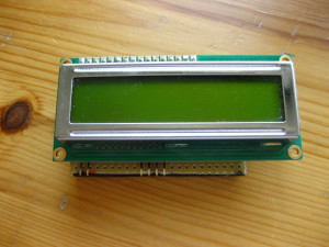
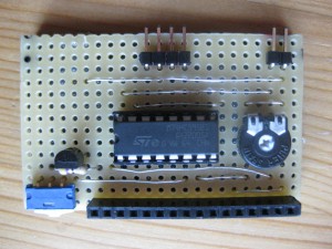
Since these displays are very cheap, I thought that it would be useful to use them as well with a Raspberry Pi. The adapter makes use of a 74HC595 shift register in order to send data in 4 bit mode to the display. It requires only three Raspberry GPIO pins to connect (Clock, Latch and Data).
| D . L C VCC GND
|
 |
Although it has been easy to find an Arduino library for driving the adapter, I could’t find instructions how to use a 16×2 LCD display with the 74HC595. So here’s a short tutorial on how to achieve this:
Step 1:
Install the Python-wrapped version of Gordon Henderson’s WiringPi2 library, which can be obtained from github.
git clone git://git.drogon.net/wiringPi

cd wiringPi

sudo ./build

git clone href="https://github.com/Gadgetoid/WiringPi2-Python.git"

sudo python setup.py install
Step 2:
Before you start attaching the display, it is important to remember that Gordon Henderson’s WiringPi2 module makes use of a GPIO naming scheme, which is different from the default RPi.GPIO Python module! Refer to Gordon’s table to avoid confusion:

Therefore, in the Python code below, we switch to the RPi.GPIO naming scheme by calling the function:
wiringPiSetupGpio()
Step 3:
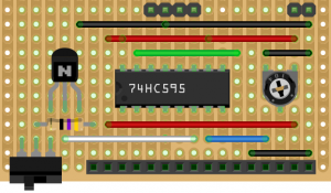
Note that WiringPi’s numbering of the shift register’s eight output pins does not correspond to it’s physical pins. In the Python code below, the shift register pins are numbered from 0 to 7, however on most 74HC595 data-sheets they are labeled with QA to QH. And to complete your confusion, output pin 1 (QA) is physical pin 15 on the shift register. Thus, make sure to remember the numbering while connecting your wires …
 Step 4:
Copy the following Python code to your Raspberry Pi.
### ------Shift Register 74HC595 PinOut------
### [SR Pin 14 (DS) Pin6, of LCD shield] to RasPi GPIO - [datapin]
### [SR Pin 12 (ST_CP), Pin4 of LCD shield] to RasPi GPIO - [latchpin]
### [SR Pin 11 (SH_CP)], Pin3 of LCD shield to Raspi GPIO - [clockpin]
### Black wire to Ground, Pin1 of LCD Shield
### Red wire to +5v, Pin2 of LCD Shield
### Pin4 of LCD Shield, DNC
###
### ------Shift Reg to LCD-----
### SR physical Pin: --- LCD Pin:
### SR Pin 15 --- ENABLE 10000000
### SR Pin 1 --- D7 00000010
### SR Pin 2 --- D6 00000100
### SR Pin 3 --- D5 00001000
### SR Pin 4 --- D4 00010000
### SR Pin 5 --- not connected 00100000
### SR Pin 6 --- backlight control 01000000
### SR Pin 7 --- RS 00000001
### lcdHome (const int fd) ;
### lcdClear (const int fd) ;
### lcdDisplay (const int fd, int state) ;
### lcdCursor (const int fd, int state) ;
### lcdCursorBlink (const int fd, int state) ;
### lcdSendCommand (const int fd, unsigned char command) ;
### lcdPosition (const int fd, int x, int y) ;
### lcdCharDef (const int fd, int index, unsigned char data [8]) ;
### lcdPutchar (const int fd, unsigned char data) ;
### lcdPuts (const int fd, const char *string) ;
### lcdPrintf (const int fd, const char *message, ...) ;
### lcdInit (const int rows, const int cols, const int bits,
from wiringpi2 import *
import time
wiringPiSetupGpio() # use RasPi GPIO pin scheme
# Set data, latch and clock pin
dataPin = 17  # DS, serial data input (data)
latchPin = 27 # ST_CP, Storage Register Clock Pin (latch)
clockPin = 22 # SH_CP, Shift Register Clock Pin (clock)
# Set pins to Output Mode - 5 Volts should never be used for Input!
pinMode(dataPin, 1)
pinMode(latchPin, 1)
pinMode(clockPin, 1)
# Assign values to 595's output pins (0 - 7)
pinBase = 100
LED = pinBase + 6
RS = pinBase + 7
E = pinBase + 0
DB4 = pinBase + 4
DB5 = pinBase + 3
DB6 = pinBase + 2
DB7 = pinBase + 1
# pinBase, num pins used, SER, SRCLK, RCLK
sr595Setup(pinBase, 8, dataPin, clockPin, latchPin)
# Init HD44780 LCD's pins
# RS, E, DB4, DB5, DB6 and DB7's signals are coming out of the 595
#lcd = lcdInit(2, 16, 4, RS, E, 0, 0, 0, 0, DB4, DB5, DB6, DB7)
lcd = lcdInit(2, 16, 4, RS, E, DB4, DB5, DB6, DB7, 0, 0, 0, 0)
def BKL(ENABLE):
 digitalWrite(LED, ENABLE)
def INIT():
 lcdHome(lcd)
 lcdClear(lcd)
 #lcdPuts(lcd, time.strftime("{c7f7cb1468c0d02af358b3ce02b96b7aadc0ce32ccb53258bc8958c0e25c05c4}d-{c7f7cb1468c0d02af358b3ce02b96b7aadc0ce32ccb53258bc8958c0e25c05c4}m-{c7f7cb1468c0d02af358b3ce02b96b7aadc0ce32ccb53258bc8958c0e25c05c4}y - {c7f7cb1468c0d02af358b3ce02b96b7aadc0ce32ccb53258bc8958c0e25c05c4}H:{c7f7cb1468c0d02af358b3ce02b96b7aadc0ce32ccb53258bc8958c0e25c05c4}M"))
def PRINT(text, col, row):
 lcdPosition(lcd, col, row)
 lcdPrintf(lcd, text)
The script can be imported as a Python module. Then, text can be sent to the display by calling the DISP.PRINT(text, col, row) function. With DISP.BKL(1) and DISP.BKL(0), one can toggle the backlight ON and OFF, respectively.
In case that you want to use different pins of your display and/or shift register, you simply have to assign the correct values to pinBase and the lcdInit() function. It is also possible to use any GPIO pin as data, latch or clock on the Raspberry Pi.
Update
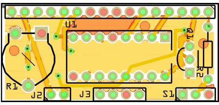
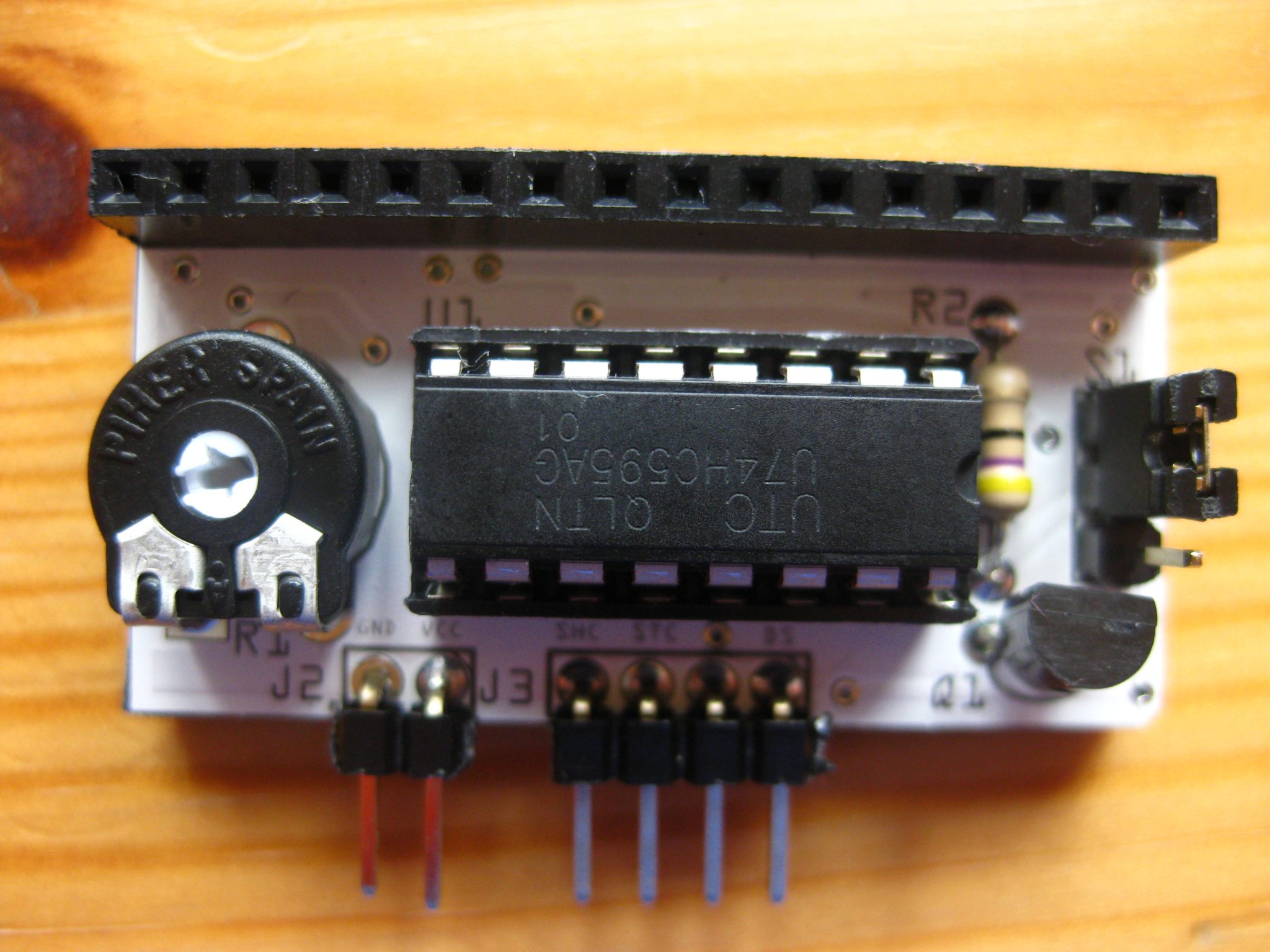
I had some spare time to design a PCB in order to downsize the 16×2 LCD backpack. Dimensions of the PCB are approx. 22 x 42 mm, which is much smaller than the former stripe board (approx. 37×59 mm). The PCB was manufactured at fritzing.org. Schematics of the PCB can be downloaded from here.
|
|