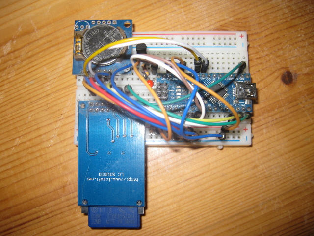
In environments without W(LAN) access, SD-Card breakout boards are very useful for recording sensor data. With only a few building parts, an Arduino Mini, a SD-Card Reader and a DS1307 RTC, it is possible to build a battery-powered data logging device, which can be assembled in less than five minutes.
Arduino modules
To get started, you need the following building parts:
- 1 x DS1307 RTC
- 1 x (Micro)SD-Card Breakout board
- 1 x FAT16 formatted SD-Card
- 1 x Arduino Mini/ Mini Pro (5 V, 16 Mhz)
- 15 x M/M Jumper wires
- 1 x Dallas DS18B20 Temperature Sensor
- 1 x Standard LED (optional)
- 1 x Half-Size Breadboard
- 1 x 220 Ω 1/4 W resistor (optional)
- 1 x 4.7 kΩ 1/4 W resistor
SC-Card preparation
SD cards come in two popular flavors – microSD and SD. Their interface, code and structure is all the same. The only differences is their physical size. Although, SD cards are ‘raw’ storage devices and they’re just sectors in a flash chip, it’s most convenient to format them to a filesystem, which can be handled by a small microcontroller, such as FAT16 or FAT32. It is strongly recommended to do the formatting with the official SD-Card formatter.
Wiring
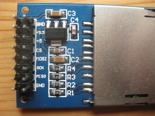
SD-cards are strictly 3.3 V devices and the power draw when writing to the card can be fairly high, up to 100mA or more. Therefore, most breakout boards have a build-in voltage regulator and logic level-shifters to allow their use on devices with 5 V or 3.3 V logic’s. For interfacing an Arduino with the SD card you have to use the SPI bus. SD cards will give the best performance when connected up to the hardware SPI pins of the Arduino. For ‘classic’ Arduinos such as the Duemilanove/Diecimila/Uno those pins are digital 13 (SCK), 12 (MISO) and 11 (MOSI). You will also need a fourth pin for the ‘chip/slave select’ (SS) line. Traditionally this is pin 10 but you can actually use any pin you like.
If you have a Mega, the pins are different! You’ll want to use digital 50 (MISO), 51 (MOSI), 52 (SCK), and for the CS line, the most common pin is 53 (SS). Again, you can change the SS (pin 10 or 53) later.
- Connect the 5V pin to the 5V pin on the Arduino
- Connect the GND pin to the GND pin on the Arduino
- Connect CLK to pin 13 or 52
- Connect MISO to pin 12 or 50
- Connect MOSI to pin 11 or 51
- Connect CS to pin 10 or 53