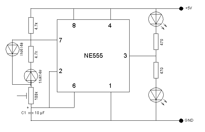
In order to test my Arduino UNO oscilloscope, I wanted to use a circuit which periodically changes voltage with a relatively low frequency. The flip-flop circuit below has a 10 µF capacitor that is periodically charged and discharged. Furthermore, the timer controls two LEDs by pulling the output pin 3 of NE555 HIGH or LOW. Both can be monitored with the oscilloscope and results in typical shark-tooh or comb waveforms.
Parts list
- 2 x standard LEDs
- 1 x NE555 timer IC
- 2 x 4.7k resistor
- 1 x 10 µF capacitor
- 1 x 100 nF capacitor (optional)
- 2 x 1N4148 diode
- 2 x 470 Ω resistor
- 1 x 100k variable resistor
- 1 x small-size prototype breadboard
- M/M breadboard wires
Mode of operation
The blink frequency is adjusted with a 10k variable resistor. Together with R1 or R2 it controls the charge/discharge rate of the capacitor. At the moment when the circuit is switched on, the capacitor C1 is discharged. The input trigger of NE555 (pin 2) is set to GND and the first cycle is started. The capacitor C1 starts to charge through the 4.7k resistor R1 and the 100k variable resistor. As soon as a voltage of 2/3 from +VCC is reached at the capacitor, the internal RS-flip-flop of NE555 is reset. The output on pin 3 is set to LOW and the discharge-exit (pin 7) switches to GND. The capacitor C1 discharges through the variable resistor R2 and the discharge-exit. As soon as the voltage at capacitor C1 reaches 1/3 +VCC, a new cycle starts.