In order to use the USB-to-serial adapter for uploading sketches to a standalone ATMega328, you must first upload the right bootloader. Instructions how to do that can be found here (you must select “Arduino Duemilanove or Nano w/ ATmega328” from the Tools > Board menu and chose “Arduino as ISP” from the Tools > Programmer menu). Remember that you’ll also need an external oscillator for this setup, consisting of a 16 MHz clock crystal, and two 22 pF capacitors, wired to pin 9 and 10 of the ATMega!
Although, it is possible using the Arduino UNO for uploading sketches to a standalone ATMega328, it requires removal of the ATMega from the Arduino board, which potentially can damage its pins. Thus, it is more safe to use an USB-to-serial converter.
Programming of the microcontroller using the USB-to-Serial adapter failed at the beginning, because of some incomplete and confusing instructions in this tutorial. So, here are some hints in case you receive the “stk500_getsync() not in sync resp=0x00” error while uploading your sketch:
- If you have an adapter with an exposed DTR pin, you MUST connect a 100 nF capacitor between ATMega328 pin 1 and DTR. In addition, connect pin 1 to +VCC via 10 kΩ resistor.
- Pin 2 (RX) connects to TX on the adapter. Pin 3 (TX) connects to RX on the adapter. Be aware that there are adapters with incorrectly labelled pins. Thus, in some tutorials TX connects to TX and RX connects to RX. It doesn’t harm your ATMega328 when these pins are mixed. Just try it the other way around if it doesn’t work.
- Make sure that you have write permissions to the serial port under Linux. If you work on an restricted account under Windows, it might be necessary to grant “full access” to the C:\Program Files (x86)\Arduino folder.
- To upload a sketch, select “Arduino Duemilanove or Nano w/ ATmega328″ from the Tools > Board menu and chose “AVRISP mkrII” from the Tools > Programmer menu.
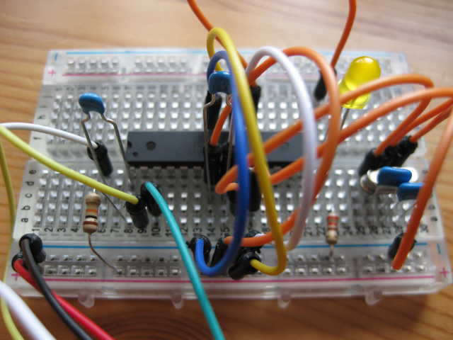
- Start with the “standard” Blink sketch for testing (connect a LED and 220 Ω resistor to digital 13 (physical pin 19 on ATMega328)).