Connecting an OLED display
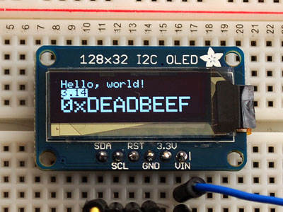
I thought it would be useful to display the current temperature, pressure and humidity values directly on the device. For this purpose, I installed an 128×32 OLED display, which connects to the RasPi via I2C bus, sharing its GPIO pins with BMP085. Only RST requires an additional GPIO pin. A Python library supporting the I2C version of the display has been ported and is available on github.

- To wire the display, I used the same pins as for BMP085, i.e. GND goes to ground, Vin goes to 5V, SDA to SDA, SCL to SCL. RST requires an additional GPIO pin on the Pi. Image source: Adafruit Industries.
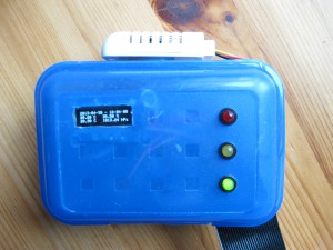
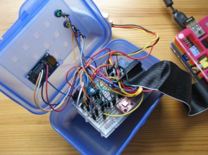
To protect my breadboard from accidental removal of jumper wires, I placed it into a small lunch box. It is even possible to close the lid without damaging the ribbon cable. The DHT22 is attached to the outer side of the box using a self-adhesive 3M Velcro strip.
Wiring three status LEDs
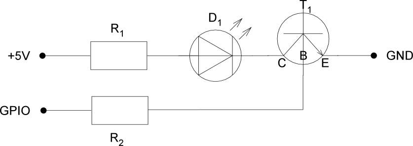
Since there were still enough GPIO pins available, I installed three status LEDs (red, yellow and green). To turn them safely ON and OFF, I connected them through a transistor circuit. There are tutorials on the internet showing how to directly wire LEDs to the GPIO pins without using a transistor. However, this is NOT recommended, because too much current going though the GPIO can damage the ARM SoC.
The 5 mm LEDs are of standard type, with 2.2 V forward voltage and a maximum current of 20 mA. Thus, it is possible to connect them to +5 V, using a 150 Ω resistor to drive the LED. (5-2.2/0.02 = 140 Ω). If you don’t know which resistor to take for your LEDs – there are many online-calculators available on the internet.
The circuit is controlled with a NPN BC547 transistor, using a base resistor of 4.7 kΩ to protect the GPIO pin from high current. With the resistor it is about 1 mA. The LEDs are controlled using the python GPIO library. To turn them ON or OFF, simply pull the GPIO pin attached to the transistor base HIGH or LOW.
To mount the LEDs into the lunch box, I drilled some holes into the lid using a Dremel. The OLED display was fixed to the lid using some hot glue.

- With a Dremel I drilled three holes into the breadbox to mount the status LED. They light up, depending on the relative humidity. Red lights up above 50 {c7f7cb1468c0d02af358b3ce02b96b7aadc0ce32ccb53258bc8958c0e25c05c4}, yellow below 50 {c7f7cb1468c0d02af358b3ce02b96b7aadc0ce32ccb53258bc8958c0e25c05c4} and green below 40 {c7f7cb1468c0d02af358b3ce02b96b7aadc0ce32ccb53258bc8958c0e25c05c4}. The tiny font on the display is hardly readable, but now one can see from the distance in what range the current values are.

