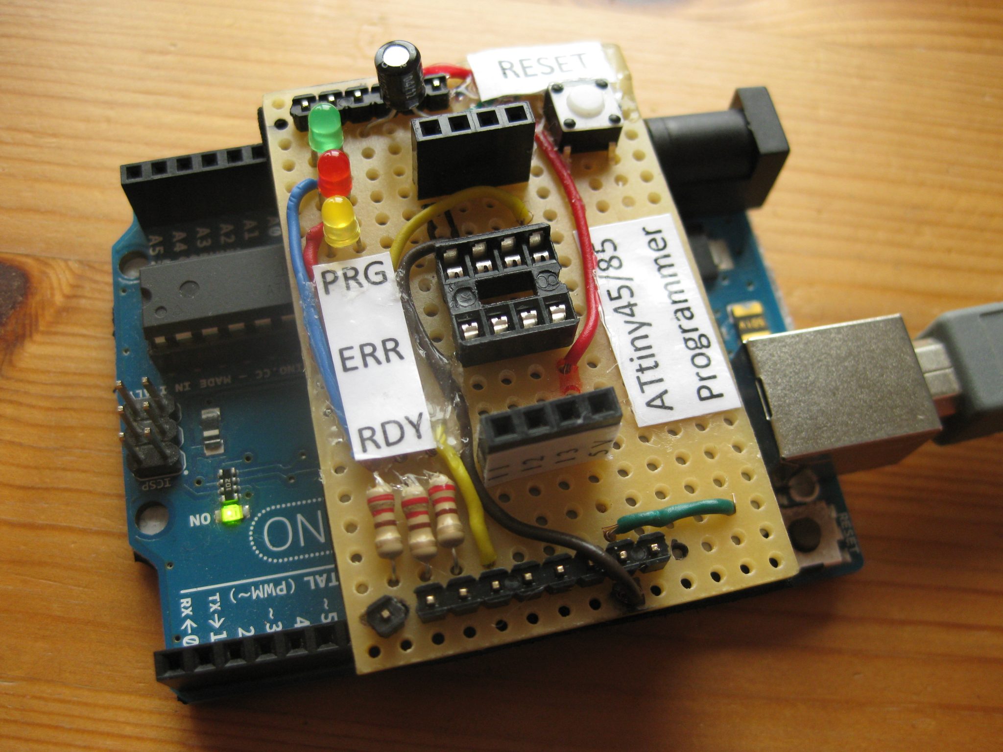
Instructions on how to upload the sketch to an ATtiny45/85 using an Arduino UNO as an ISP can be found on this page. If you’re going to program ATtiny45/85 microcontrollers more often, it is reasonable to build an ATtiny45/85 programming shield for the Arduino UNO. Again, a tutorial can be found at Instructables. I have modified this shield by placing an LED (with resistor, 220 Ω) on the following Arduino pins:
- 9: Heartbeat – shows the programmer is running
- 8: Error – Lights up if something goes wrong (use red if that makes sense)
- 7: Programming – In communication with the slave
In addition, I included a push button between the 10 uF capacitor (+) and ground in order to RESET the Arduino after flashing without removing either the shield or USB plug. The 2×4 female header pins give access to the ATtiny pins, so that one can add a resonator shield or route them to a breadboard, e.g. for ATtiny44/84 programming.
Update
Meanwhile I started experimenting with ATtiny44/84 and ATiny4313 microcontrollers. I’ve discovered a nice Arduino shield for programming Amtel microcontrollers which was designed by Jeff Murchison. Shields were out of stock at the time of writing, thus I dowloaded the fritzing project files from github and ordered a PCB at fritzing.org. It saved me from hassle with customs as well, since Jeffs boards are shipped from Canada.
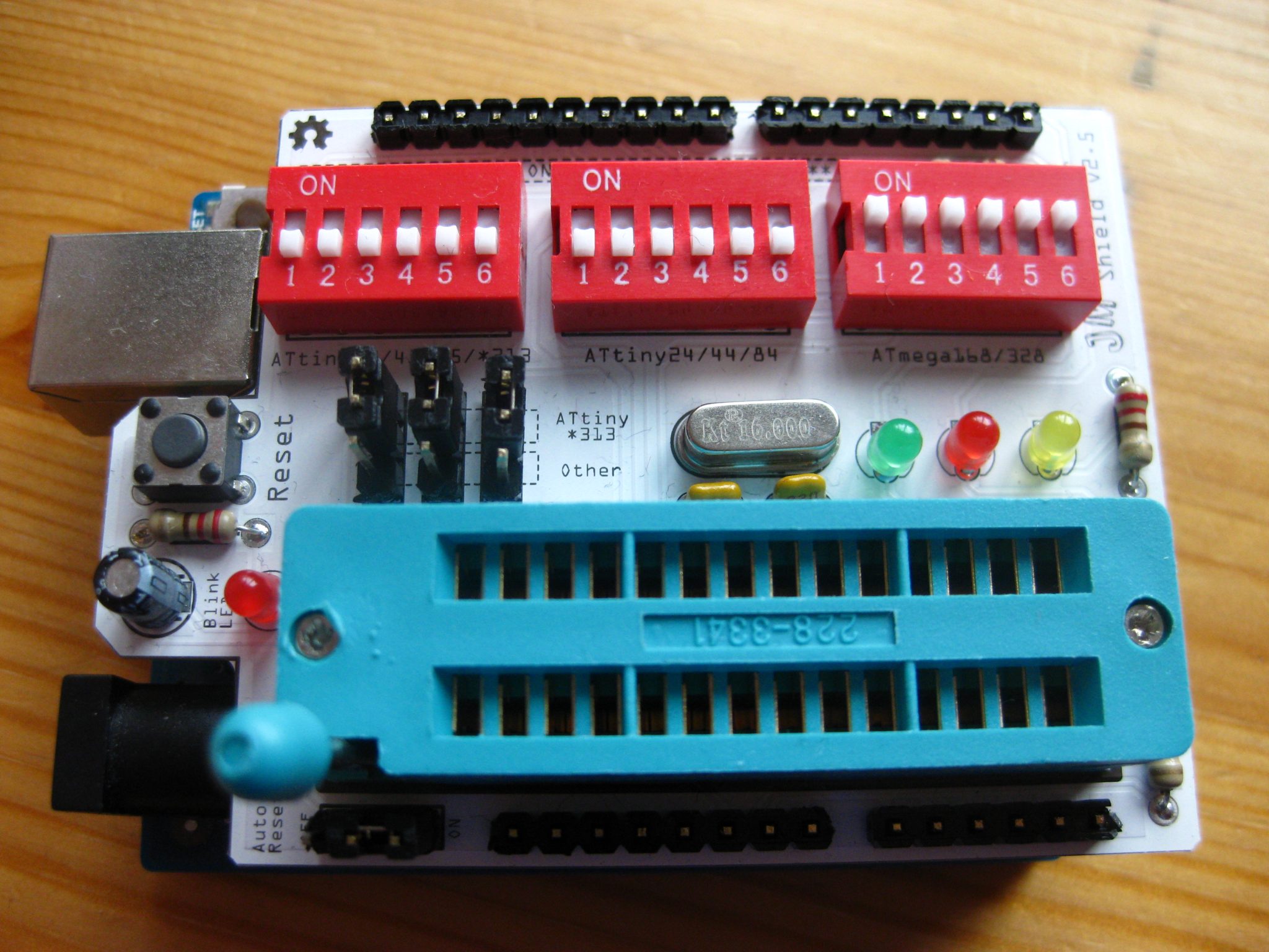 Parts can be ordered elsewhere, however you must take care that the spacing of the ZIF socket and DIP switch pins is 2.54 mm. The standard LEDs (2.1 Volt UF) used here require 220 Ω resistors.