Thermal sensors, such as DS18B20 can be connected to the Raspberry Pi via 1-wire bus. However, the 1-wire bus is not implemented in hardware, but only as software emulation on GPIO4, which has some major disadvantages. The 1-wire data link is acting as a very long “antenna” which catches interference. All GPIO pins of a Raspberry Pi are directly connected to the CPU. So every interference cought on 1-wire bus is transported directly to the Broadcom SoC. Furthermore, the 1-wire protocol needs a very tight and time-critical signal generation, so it’s resource-consuming to communicate with 1-wire slaves and therefore highly unreliable if running on a non-real-time operating system.
I noticed that the DS18B20 sensors, which I have wired to my Raspberry, return at least once or twice a day bad temperature values, making it impossible to retrieve reliable max/min temperature data.
I recently stumbled upon a DS2482S-100 1-wire master breakout board that allows to control one or many 1-wire slave devices by simply sending I2C commands, relieving the task of generating the time-critical signals the 1-wire protocol requires. It provides bidirectional protocol conversion between an I2C master and 1-wire slave devices. The breakout board makes use of a DS2482S-100 converter, that is exclusively sold in a SO-8 package which doesn’t fit onto a breadboard.
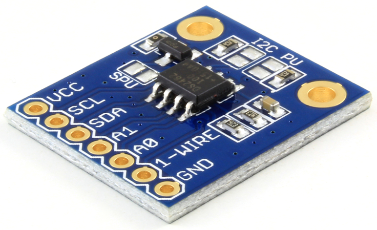 The breakout board is very simple to use. All you need to do is connecting VCC (3V3), GND, SDA and SCL to it’s counterparts on the Raspberry Pi GPIO header. As usual, the DATA pin of DS18B20 is connected to the pin labeled with “1-wire”. Don’t forget to connect a 4K7 pullup resistor between VCC and DATA of DS18B20. Continue reading How to make the 1-wire bus more reliable on a Raspberry Pi