Since spring has almost arrived, I wanted to check how many birds are still coming to my feeder before removing it from the balcony. Good to have a Raspberry Pi for counting our feathered friends!
There are several ways to detect motion with a Raspberry Pi. The best and most popular method is connecting a PIR sensor, which detects the infrared radiation emitted or reflected from an object. Motion can be also detected by image processing of webcam frames with a software called motion. However, image processing requires CPU power, which is limited on a Raspberry Pi. Furthermore, motion detection with a webcam depends on decent light-conditions and may be triggered from inanimate objects, such as trees or leaves moved by the wind.
Here I wanted to test whether it is possible to count bird visits using an infrared light barrier. I had both a photo diode and a high power infrared LED lying around in my tool box (SFH230-FA and SFH4550). Consider this project as a “proof-of-principle” build and be aware that there are more reliable ways for detecting motion!
Since the SFH4550 has a narrow emission angle of 3°, I designed a circuit which allows to sense the light reflected by an obstacle which moves into the IR beam. The setup is very similar to IR range sensors used in robotics. The detection range is about 30 cm, which is decent to monitor the space within the bird feeder. Furthermore, the diodes are about 0.64 € each, which is much cheaper than a ready-to-use IR distance shield.
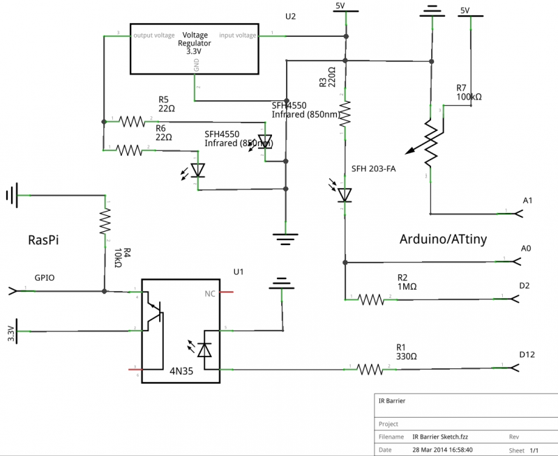
The high power infrared LEDs have a forward current of IF = 100 mA which is too much for powering the RasPi, webcam, WLAN dongle and LCD display from a single 1 A power supply. Therefore, I designed a circuit using an Arduino/ATtiny84, that passes the HIGH/LOW signal for triggering the camera via an 4N35 optocoupler to the Pi. I’ve included a 3.3 voltage regulator, because the IR LEDs have a VF of 1.5 V. If supplied with a voltage of 5 V, 1/2 Watt, 40 Ω resistors would be required (3.5 V x 0.1 mA = 0.35 Watt), which I haven’t had in my toolbox.
To prevent that stray light reaches the diode, I glued a coil of black electric tape around it.
With the 10K potentiometer one can adjust the threshold level to set D12 HIGH. The A0 values can be sent to the serial monitor. Because this is not practicable when the device is used outdoor I attached a 16×2 LCD to display sensor readings and threshold. The LCD is controlled by a 595 shift register, so that only three Arduino/ATtiny84 pins are required.