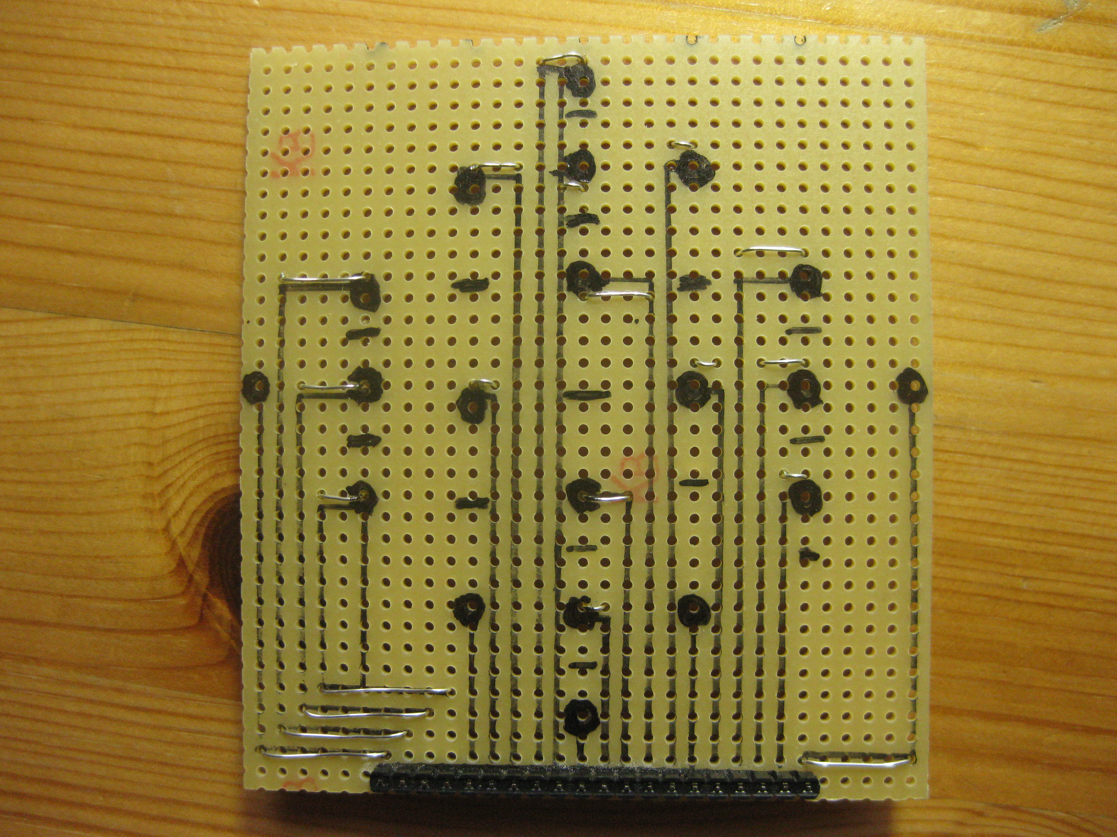
After assembling the cube, the 16 anodes and wires attached to each plane must be connected to a micro controller. For this purpose, I used a stripe board, onto which I transferred the pattern of the building slab in order to mark the positions of the soldering joints on the stripe board. All soldering joints are routed to a 20 x 1 header which serves as an interface to the micro controller port. I labelled the anodes in clockwise direction, starting with the leftmost column. Therefore, the header pins have the following order:
1, 2, plane A, 5, 9, 6, 3, 4, plane B, 13, plane C, 10, 7, 8, 14, 11, 12, plane D, 15, 16
Since the 64 LEDs are controlled by multiplexing, the cube requires in total 20 output pins. An ATMega 328-PU is sufficient for this purpose. Instructions how to place it on a stripe board can be found with a Google search for “Arduino on a strip board“.
For the controller board you need the following parts:
| Stripe board, 2.54, approx. 9.5 x 9.5 cm | 1 x |
| 330 to 100 Ω Resistor (depending on the type of your LEDs) | 16 x |
| 10 kΩ Resistor, 1/4 W | 1 x |
| 16 MHz crystal | 1 x |
| 12 pf capacitor | 2 x |
| 100 nf ceramic capacitor | 2 x |
| 2 x 3 male pin header | 1 x |
| BC337-40 standard transistor | 4 x |
| 1 kΩ resistor. 1/4 W | 4 x |
| ATMega328-PU | 1 x |
| 5 V Voltage regulator, L7805CV (or equivalent) | 1 x |
| 10 uF capacitor | 2 x |
| 12 x 1 female header | 1 x |