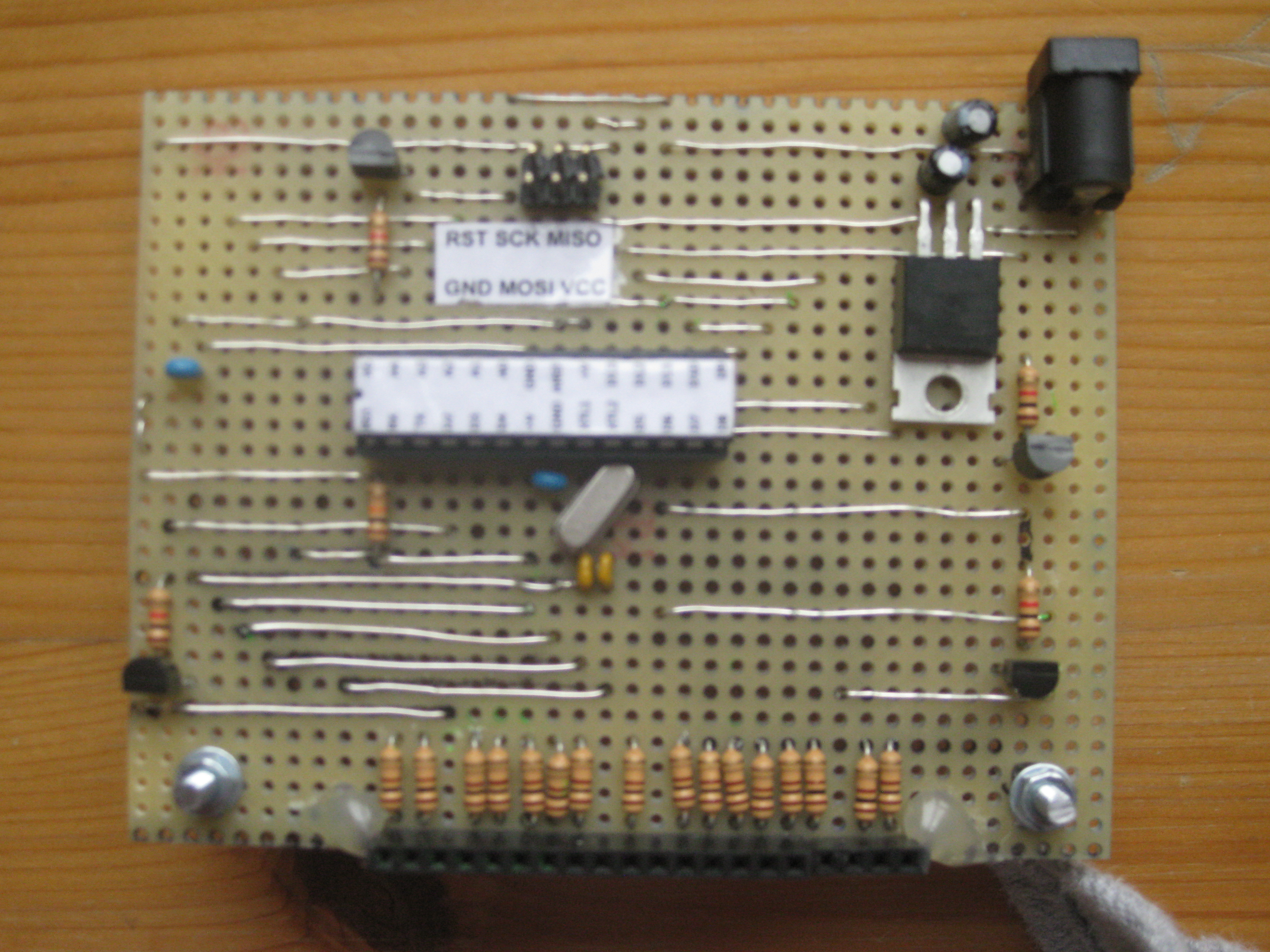
All output pins are routed to a 20 x 1 pin header. In addition, all column pins are equipped with resistors matching your LED specs (here: 100 Ω) and all plane pins are routed to BC337 (NPN) transistors with 1 k base resistors. In addition, I added an ISP header for programming the ATMega. I also included a 5V voltage regulator for connecting it to a wall charger or battery pack. The controller board can be stacked underneath the cube’s base.
 |
 |
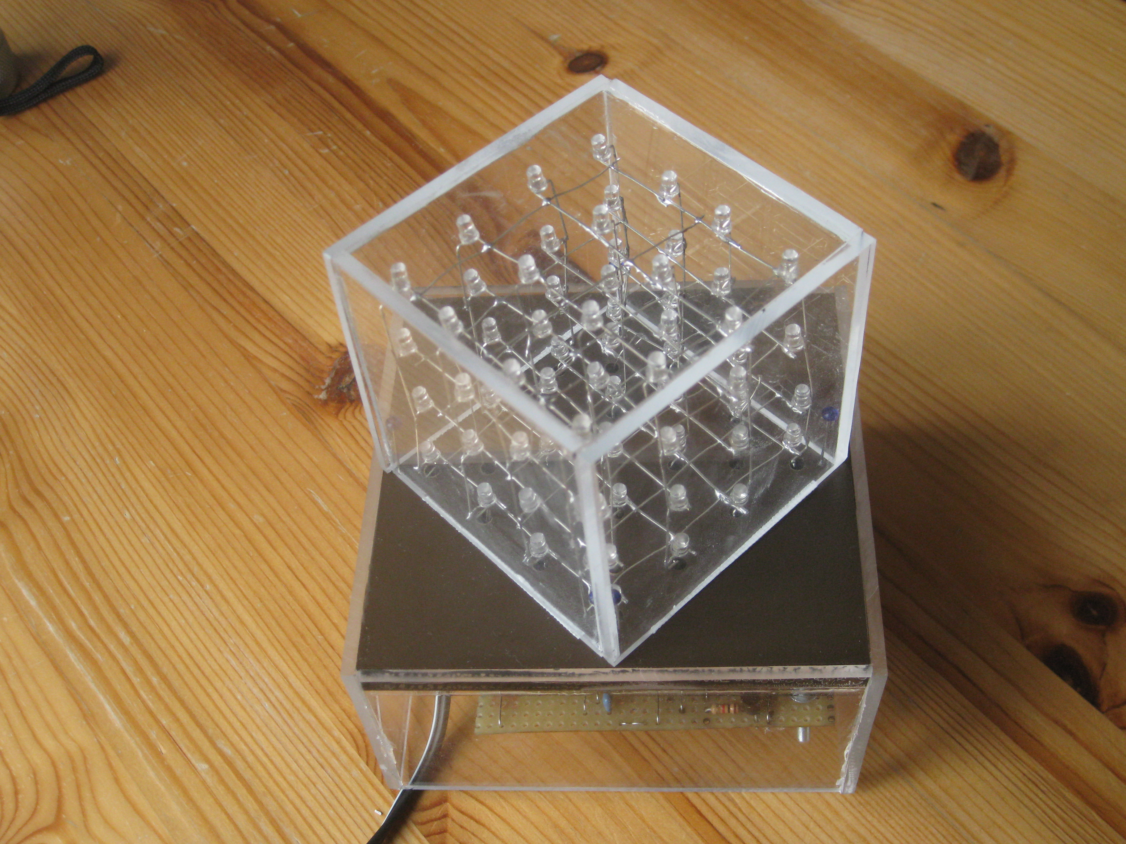
To protect the hardware I enclosed both, cube and controller in a box made of 3 mm acrylic glass.
For programming the cube, I used the Arduino IDE. One can find a lot of pre-made shows for the cube, as well as a code generator to make your own show. Depending on the layout of the controller board, you have to adjust the order of output pins in the sketch. Edit the lines reading:
int ColPin[] = {0, 1, 17, 18, 3, 16, 8, 9, 4, 7, 11, 12, 5, 10, 15, 14};
int PlanePin[] = {2, 19, 13, 6};
If you notice that whole columns/planes light up, you must change all lines containing digitalWrite( ) statements from HIGH to LOW and vice versa.