So far I’ve attached devices to my Raspberry Pi or Arduino Uno with ratings less than 100 mA. These devices were connected to the output pins through a transistor or optocoupler. However, for heavy load currents a relay must be used. As a noob, it is somewhat difficult to chose parts with the right specs for driving a relay — so here are some hints.
Driver circuit
The driver circuit should be arranged as on the scheme below. The digital output pin of the microcontroller (J1) is connected through a resistor (R1) to the base of transistor Q2. The collector of Q2 connects to +5V and the emitter to the relay coil. A free-wheeling diode is inserted across the coil.
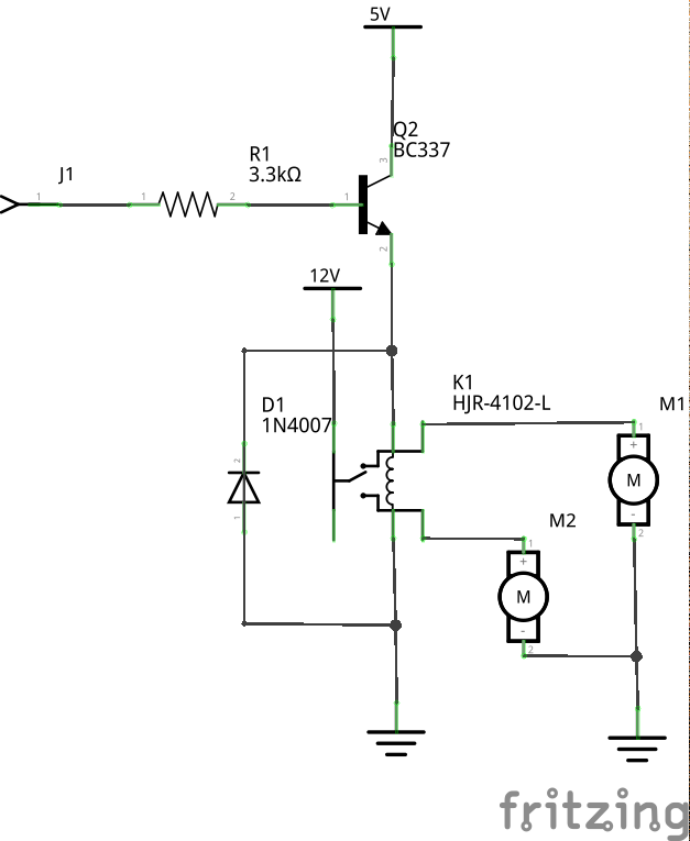
To build an Arduino/ATtiny relay shield, I used a 5 Volt HJR-4102-L mount relay, with a coil resistance of 125 Ω. Thus, the collector current (Ic) of the transistor should be at least 2 x 5 / 125 = 80 mA. The popular BC337-40 transistor can handle up to 800 mA and therefore has the right specs to drive this relay.
Calculating the size of the base resistor, R1
The DC gain (hFE) of BC337-40 is about 250-600. Since there is no hFE(SAT) given in it’s datasheet, we calculate with an estimated hFE under saturation of 250 / 3 = 80. In order to reach a coil current of ≤ 80 mA, the transistor base current (IB) must be at 1 mA (IB = Ic / hFE). According to it’s datasheet, the transistor base of BC337-40 can deal with a current of 100 mA. An Arduino UNO pin can handle up to 40 mA. Thus, we’re not exceeding the limits.
The Arduino UNO microcontroller can deliver up to 5 Volt (minus 10 {c7f7cb1468c0d02af358b3ce02b96b7aadc0ce32ccb53258bc8958c0e25c05c4} tolerance = 4.5 Volt at 1 mA). With a voltage drop of 0.7 V between base and emitter, we can now calculate the size of the base resistor as: Rb = (4.5 – 1.2) / 1 = 3.3 kΩ.
Arduino/ATtiny relay shield
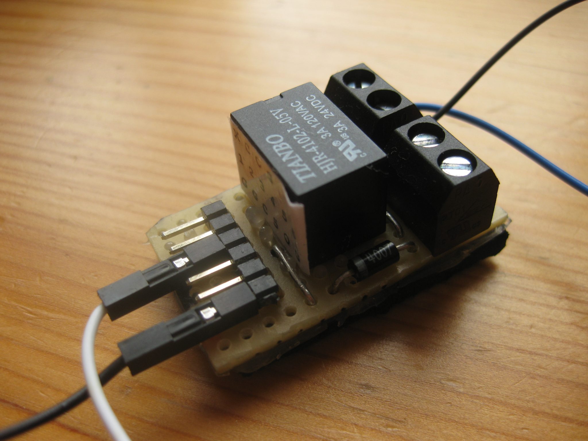 I placed the relay on a small piece of stripboard together with the free-wheeling diode and a 6 x male pin header to access both relay coil and switch pins.